
Authorization Letter
October 23, 2017
We apologize for the delay, this notice is being provided to approve your proposed amateur radio station in the 472.0 – 479.0 band(s) at the following coordinates: . UTC has determined that your proposed amateur radio station would not operate within a horizontal distance of one kilometer from a transmission line that conducts a power line carrier (PLC) signal in the 472.0 – 479.0 bands.
Please direct any questions to the undersigned.
Mike Etzel
202-833-6839
End of Letter
630 meters (and it’s partner, 2200 meters) were given official permission by the F.C.C. to operate as of October 16, 2017. I hope to operate 630 meters with JT9 and WSPR (and maybe even FT8). A process to register a station has been implemented to notify power companies of amateur operation. Of course, W0QL filed an application immediately. The FCC notice started off a long list of action items to get done before we can get on the air. We made some quick decisions.
- Antenna: Possibility one – The existing 6 meter antenna is mounted on a 39 foot aluminum mast. That mast could be pressed into service right where it is as the vertical portion of an inverted L antenna. The plan is to lay radials around the base of the vertical after cutting the weeds to make room. A thin wire will run from the top of the mast over to the top of the 20 meter tower about 200 feet away. Plans came from this article: http://www.wd8das.net/630mPractical.pdf
- Possibility 2 – There is an unused ground screen in place we could erect a vertical over. It was used unsuccessfully for the 6BTV vertical.
- Possibility 3 – Use existing big vertical with a relay to switch from current operation to 630 meters.
- A variometer will be built to resonate and match. The variometer is under construction using scrap pvc pipe. Plans for the variometer came from http://www.g0mrf.com/variometer.htm.


- Rig: Possibility 1 – Luckily the existing Kenwood TS-480 receives down to the operating frequency for 630 meters, 474 kHz. Antenna port 2 can be used leaving antenna port 1 in tact for the existing station. A 630 meter downconverter has been built that provides 20 watts output from 1 watt input. The TS-480 minimum power output is 5 watts so we will need an attenuator in the line when transmitting. With a relay driven by the PTT line the attenuator can be bypassed for receiving.
- Possibility 2 -Also under consideration is the K3 because it can put out 1 watt and wouldn’t need an attenuator.
- Possibility 3 – The Yeasu FT-817 puts out a 1 watt or less signal in the 80 meter band that could drive the downconverter. This arrangement has been bench tested and the output is 15 watts at 474.2kHz. Perfect for a 10 per cent efficient antenna. The FT-817 already has the necessary hardware interface and software running on a Intel Compute Stick from an earlier wspr project. It can be diverted to 630m use.
In all cases possibility 3 seems most viable.
U.S. Amateurs will be allowed to run a maximum of 5 watts EIRP, which is about 1.6 watts ERP. The short antenna will be inefficient relative to a full size dipole (991 feet long) and should keep us legal. Radiation resistance is estimated to be .4 ohms and ground loss 6 ohms. That gives us efficiency of 6.25 per cent. Our 20 watt downconverter would radiate 1.375 watts erp and be compliant with the regulations.
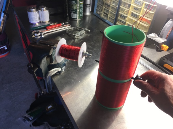
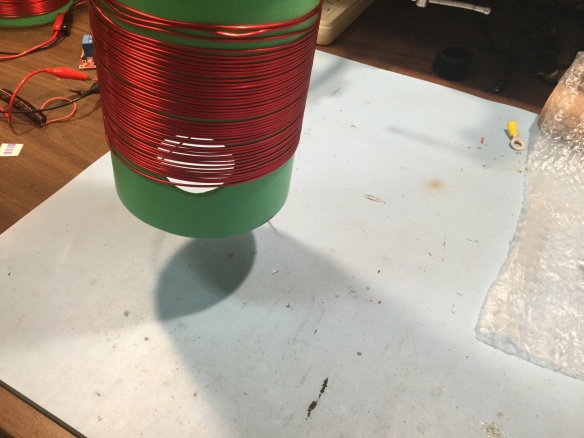
The magnet wire arrived in the mail today. This will become the winding for the variometer — 325 feet of 16 awg.

The coils are wound:

UNfortunately, the coil only measures 800 micro henries and we need 1900 according to the online calculator. The eBay listing said the diameter of the wire is 0.0520″. Two hundred turns would be about 10.4″. I might try it temporarily on the big vertical in Strasburg.
September 30, 2018 – Moved from the back burner to the front burner after a year hiatus. A 630 meter antenna is in the air and matching is almost done. A new rig capable of transceive on 630 meter is being broken in.
The transceiver is the Icom IC-7300 with a wide-band modification which has come out over the past year.
http://radioaficion.com/cms/ic-7300-wide-band-modification/
The mod enables transmitting on 630 meters at a power level of 30 watts. An antenna with an efficiency of 5 per cent would put out an EIRP of 5 watts. Five per cent is much easier to achieve than the 10 per cent we had been shooting for with the 15 watt converter. Also fewer cables and fewer boxes to get working. HRO offers to do the mod for $40.
Antenna consists of a vertical with a top hat and a loading coil at the base. The top hat is a tee which is 50 feet long on each side. The vertical is 36 feet tall. Two radials are each a 50 feet long welded wired fencing laid on the ground. Two more radials are 100 feet each. Thin white wire is used for the vertical and is very hard to see in this picture extending vertically from the white box.

The loading coil enclosure, radials, and the first few feet of the vertical can be seen in this pic.

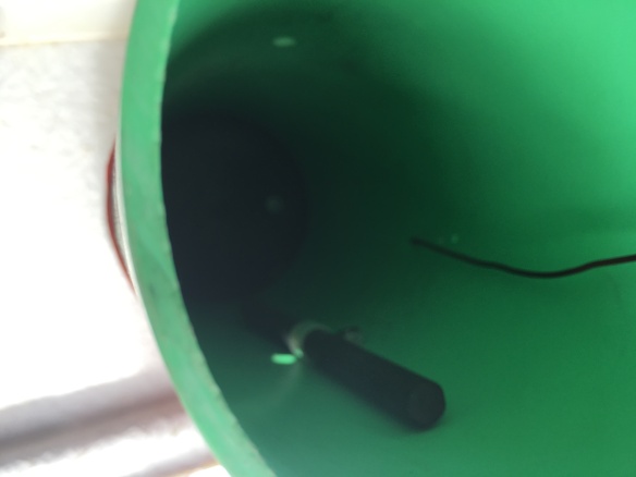
This is the loading coil. It’s modified from the variometer that was wound a year ago. The black plate holding the coil in place is the lid from a Cisco Kirkland candy container. It fits the 4.25 ” coil diameter perfectly .

It was found that a ferrite rod inserted into the center of the coil changed the inductance as effectively as the variometer coil. The rod is much easier mechanically. It is mounted inside the coil using a P clip. Tuning is accomplished by sliding the rod up and down, a lot like aligning the i.f. strip on a radio. It doesn’t need to be centered. Mounting it on one side of the form worked perfectly.
Measuring with the new RigExpert AA-55 antenna analyzer the rod could be adjusted for perfect resonance.
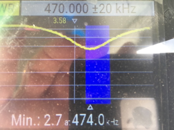
As one can see the swr is 2.7 which is unacceptable. Multiple taps were made on the coil when it was wound. Unfortunately the lowest tap is too high. It was placed at 4 turns up from the bottom and reads 116 ohms. Plans are to unwrap some of the turns from the bottom and re-resonate the system once 50 ohms is reached. That should provide a 1:1 match.
Efficiency
To calculate efficiency the formulas of Phil Salas, AD5X, are used.
Rr = (Actual length ÷ ¼ wave length)squared x 36 ohms
Quarter wave length at 474.2 KHz = 234/.4742 = 493 ft
This vertical is 36 ft tall.
36 ft / 493 ft = .0795
.0795 squared = .0053
.0053 X 36 ohms = .19 ohms Radiation resistance, Rr
Efficiency is 100 X Rr / (Rr + Rg) where Rg is total loss in ohms ( mostly ground loss ) Assuming 10 ohms of ground loss:
.19 / 10.19 = .0188 or approximately 2 per cent efficient.
30 watts in produces .56 watts out, ERP. This should be well within the legal limits of 1.6 watts maximum, ERP. We hope the ground loss is less than 10 ohms but we currently have no way to measure it. If we use the 6 ohms mentioned early on this is what we get.
.19/6.19 = 3 per cent .03 X 30 = .9 watts (Still within FCC limits)
Meanwhile the new IC-7300 is burning in as well as a new Intel NUC computer.
Loading Coil update: Removing some of the turns from the bottom worked but a 50 ohm tap for the coax could not be obtained. It showed up a new problem. Now the bottom tap is too low, 9 ohms. Clipping onto the next tap up produces 160 ohms. The taps are too far apart. Restoring some turns to get the bottom tap up to 50 ohms did not work. Each turn is too far from the 50 ohm sweet spot. Time for a new plan.
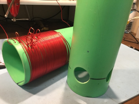
New plan: A coil form where every lower turn is accessible and can be tapped at quarter turn locations much like a B&W or Airdux coil. A new form was crafted by drilling four holes near the bottom. Instead of loops for the tap the holes will allow a clip to connect to the turns after scraping off the varnish insulation. Here is the old style beside the new coil form, again made using good ole scrap sewer pipe (new, of course).
Fully wound and measured using a Banggood tester. A Wavetek Meterman was also used to verify the readings. The range is 390 uH to 470 uH by sliding the ferrite rod up and down. Notice the rod extending from the top of the form, held by a p-clip.

The holes are visible at the bottom where a tap for the 50 ohm coax will go.
Next task is to put the coil in place at the antenna site and slide the rod to obtain a dip. Then we’ll hunt for a 50 ohm tap point.
A goal is to get on the air with 630m, even if it’s a year late of the first day of operation, October 16, 2017.

