Rework – .Reconfiguring four separate solar panel arrays, four separate controllers, and four separate batteries into one single array, one new controller —combining the batteries on one bus bar produces improved performance.
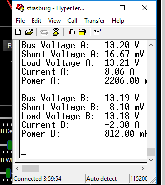
Finished product display looks this, a very easy to understand user interface from Victron.

Two Steps – Paralleling batteries, then replacing solar charge controllers.
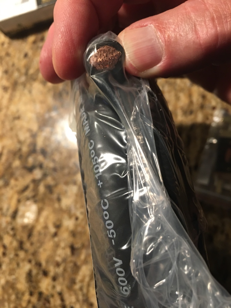
In the past, with four separate power lineups, one or the other was frequently running down or malfunctioning. By combining the components, reliability is expected to increase. Step one was to combine the various LifePO4 batteries into one battery with a bus bar. Combining different age and different capacity cells is allowable with LifePO4 (see sources in Bibliography). Their voltages change so little over their discharge curve and their life span that they don’t fight each other like lead acid batteries do. Often bus bars are rectangular copper or aluminum bars. In this installation 1/0 copper welding cable was chosen instead solely because it’s so much easier to bend. It has a nominal ampacity of 150 amps, similar to a rectangular bus bar. Each end of the cable has a terminal block where the components are connected to the bus bar. In the pictures, first is the north end of the bus bar, then the south end. The ends are about 8 feet apart.

Although it’s hard to tell in these pictures, the load and charger leads are connected in opposite corners of the bus bar to equalize the load and charge for the batteries. If the leads were connected at the same end of the bus bar the closest battery would get over exercised and age faster. The clue in these two pictures is that in one picture there are more positive (red) cables connected. In the other picture, there are more negative (black) leads connected.

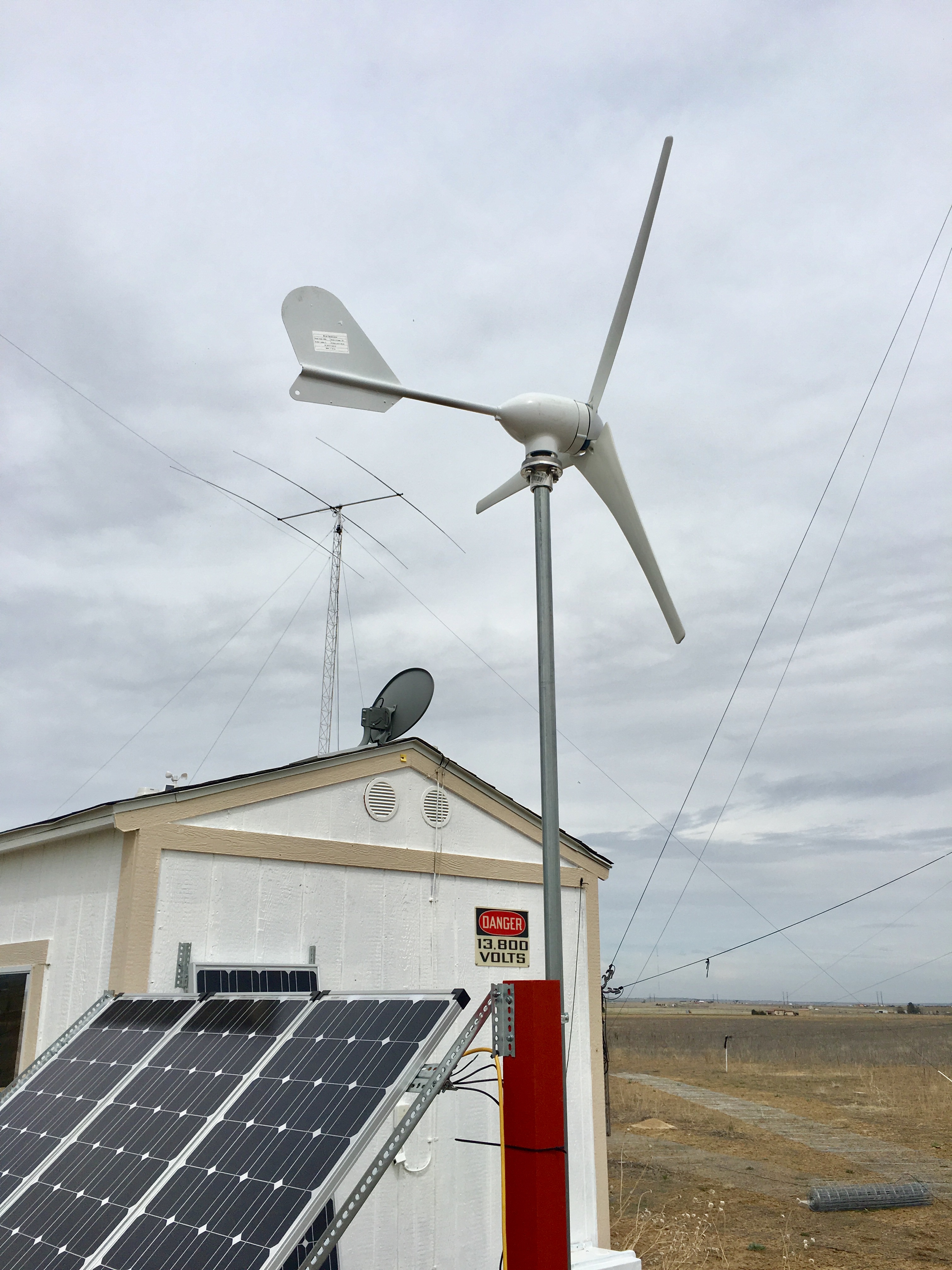
Step two was to replace the four existing controllers with one larger capacity controller. This provided a good chance to upgrade to more features and a better user interface. The brand chosen is Victron Energy. Efficiency was also improved by changing from PWM to MPPT. The new controller needed to handle the voltage from combining the arrays and the additional current from the combining. The model chosen is the MPPT 100|50, which maxes out at 100 volts and 50 amps. The panels are wired to put out nominally 24 volts and 36 amps. A Victron Cerbo GX interface was added to provide Internet access for monitoring and configuration. Older Victron components are already on site accumulated over the years — a 24volt to 12volt 70 amp buck converter, a 250 watt 24volt to 120vac inverter, a 3000watt 24volt to 230volt inverter, and finally a BMV700 battery monitor. All the Victron components communicate with each other using a simple data cable, allowing the GX to show all sorts of information graphically and remotely as in the photo at the top. Below is a shot of the new GX and MPPT controller.

Conclusion
The project was completed by dressing the cables and mounting the components on better back boards. It looks like this is the final design and although it has only been running for a few days, no issues exist. A few issues occurred and were easily resolved. Victron products are very elegant but sometimes confusing to configure. Sooner or later everything fell into place. Today, a January day about a month from the winter solstice, where the batteries had been discharged by yesterday’s and last night’s radio operation, charging only took one hour and ten minutes. That is much faster than the old PWM charge controllers. As for reliability, time will tell. Watch for updates. One of the nicest consequences of this project is getting rid of all the cludged-together hardware and software to keep the old system running. That includes the Node Red backdoor Raspberry Pi’s and the APRS status transmissions. This new system is so reliable so far that none of that 3rd party monitoring stuff is needed.
Bibliography
Sources to support this project: – A source to validate dissimilar LiFePO4 batteries can be safely connected in parallel is below from DIY Solar.
Off-Grid Garage has also been found to be a good source for all sorts of Victron Energy information needed for configuration and testing, as has DIY Solar.
Victron settings came from Off-Grid-Garage video “How to set your MPPT Solar Charge Controller for LiFePO4 batteries”. Key settings:
Absorption voltage: 3.45 V per cell or 27.6 V for the W0QL 24 volt system
Float voltage: 3.35V per cell or 26.8 V
Absorption time: 1hr (W0QL went to 1:15)
Tail disabled
The settings are posted on the Off-Grid-Garage website: